


2017版,AMD1最大的差异就是添加了了关于DC输入的产品的定义与说明。这个问题在通信-48V通讯系统中曾出现过这样的问题,但我个人碰到过的CDN都还没出问题,但是个别12V 或24V DC输入的系统在接入CDN就会出现在CDN输出端没有输出的情况,注意当时根本还没有施加SURGE,很高兴标准为此变更,我们当时考虑是CDN内的大电感与DC/DC单元谐振,所以在DC的滤波电路里特意添加了大的电容(1000UF),从而让CDN能正常供电,这一方法我们一直使用,同行们在碰到这个问题时,我个人一直建议去做这样的变动,注意CDN的DC输入我们依然使用适配器或者DC源。
1. 开篇就全文阐述了AMD1的缘由
INTRODUCTION to the amendmentRationale:
The method for testingDC products in the current revision of IEC61000-4-5 is causing many fieldrelated problems for test labs and manufacturers. Many products will not powerup through the power CDN in the standard and in some cases may be damaged bythe inductance that is necessary to apply the surge (see 77B/734/DC for furtherinformation).The DC./DC converter problem is related to the switching of theconverter which produces a voltage drop at the decoupling inductors on one handand oscillations produced by the EUT impedance in combination with the sourceon the other hand. Measurements were performed using different brands of CDNswith a device known to show that problem as an EUT. The result shows differentoscillations and signal forms of the voltage at the EUT for different CDNs.According to the outcome, the use of a CDN with a higher current rating (i.e.smaller decoupling inductivity) can solve the problem. At the meeting ofSC77B/MT12 in Akishima, Japan on August 26, 2016, it was decided to add astatement into 7.3 allowing surge tests with higher current rated CDNs and toadd a new Annex I to explain the problem in detail.
2. 增加了附录I
主要描述了DC不能正常通过CDN的成因。成因1是因为CDN是为工频设计的,而开关电流不能平滑通过CDN,成因2就是我前文所说的,CDN与源与负载形成了谐振导致的。
第二部分主要描述了标准为了应对这一问题所给的策略,即建议采用电池供电(针对成因1),并串接电阻-二极管组成的阻尼电路(针对成因2谐振)。电阻阻值并未详细列出,只是要求保证电平在误差范围内,同时不能影响SURGE正常波形。这一点到时候又是五花八门的策略,个人认为标委会的可以给些指导值,即使现在不给,后面可以详细研究再给。
Annex I
(informative)
Issuesrelating to powering EUTs having
DC/DCconverters at the input
I.1 General
As industry mandates energy saving equipment design, especially in classic data server ‘farms’ and central office locations that can contain hundreds or thousands of server/router communications equipment running continuously, the equipment manufacturers are redesigning their equipment to be more efficient and less wasting of energy in the form of heat dissipation. One of the largest wasteful components has been the power supply. By designing the equipment power supplies to operate from DC voltage and then converting the nominal input voltage to the voltages required by the circuits of the system, vast amounts of energy can be conserved when using modern switching design controlled by microprocessor technologies to only draw power from the source when actually needed by the loading circuits. Larger storage capacitors formerly used to store energy between conduction cycles are being eliminated or reduced dramatically. The result is that the input current of such DC/DC power supplies is no longer true direct current. It has become pulsed current. The frequency of this pulsed current is often a problem when passing through the inductor used in the decoupling network of the CDNs. The inductance of the decoupling network was selected to provide very low reactance to DC and AC power line frequencies typically up to 50 Hz or60 Hz. As frequency increases, so does the inductive reactance. Thus, for a surge impulse having 1,2μs rise time and 50μs duration, the reactance becomes very high and effectively attenuates the surge impulse from passing through to the source supply connected to the CDN. The surge impulse is therefore ‘steered’ to the EUT output of the CDN. The frequency of the input current pulses of DC/DC converters is evolving to faster and faster speeds to more effectively increase efficiency. As these switching supply technologies are evolving to use PWM(pulse
width modulation) techniques, the input current of these supplies is becoming a complex waveform actually containing many frequencies and their harmonics (due to the square wave nature of the pulses). As a result, the decoupling inductor, through which this current flows to its source, cannot pass these rapid changes in current. Its high reactance to these high frequency transitions causes the voltage supplied to the EUT to drop instantaneously. Because the EUT supply has little capacitance to ‘hold up’ voltage to its loads, its output voltage drops. This can cause the load equipment circuitry to stop working or to perform erratically. The DC/DC supply has rapidly responding circuitry so it immediately attempts to draw more current from its source. It would change its PWM (duty cycle) to increase current from the source. This change effectively changes the frequency of the chopped current through the decoupling inductor which can further reduce instantaneous voltage to the EUT or increase it depending upon frequency effect of the PWM, and the cycle starts over again.
Another issue for active DC/DC converters is that the presence of an inductance between the DC power source and the DC/DC converter input can cause self-oscillations due to the dynamic voltage/current ratio of the input signal. dI/dV is negative for small excursions from the nominal voltage, and for some converters this in combination with the gain/phase properties of the converter control loop can cause unwanted self-oscillation. The stability margin of the DC/DC converter in combination with the surge CDN is in general not known by the testing laboratory.
While the switch to EUT power supplies is evolving to employ more energy efficient DC power inputs to such telecommunications EUT equipment, test laboratories should acquire DC power supplies to supply power to the inputs of the CDNs used for compliance testing to power up those EUT products. Modern technology has also changed the world of laboratory DC power supplies. Today these supplies also use switching mode technologies and have very sophisticated circuitry employed to keep their output voltage and current constant under a variety of changing loads while also reducing wasted energy in the form of heat, unlike the aging linear power supply technologies. This circuitry can pose a problem when powering up devices having DC/DC converters on their inputs due to the changing current and complex current waveforms caused by the switching frequencies of those DC/DC converters. The DC source supplies might not be able to cope with such rapid changes in load. Also their output impedance, when coupled to the CDN decoupling inductance and load inductance of the EUT, could make them susceptible to oscillation. Additionally, many of these DC supplies cannot tolerate or cope with the effect of any residual surge impulses passing through the decoupling network and can be damaged. Test engineers should really study and understand the limitations of such supplies as used for compliance testing to ensure their suitability for such applications.
I.2Considerations for remediation
If a cause has not been found for the EUT not to power up through the CDN, the next step is to determine if the issue is due to the decoupling inductance limiting voltage to the EUT or whether the source DC supply is unable to maintain its output voltage, is oscillating or a combination of both. These are not always simple tasks to determine. Simultaneously viewing the input voltage and line current to the EUT with a dual channel oscilloscope can reveal whether there are oscillations or switching frequency spikes affecting the input voltage to the EUT. It is essential to have knowledge of all switching frequencies of the EUT supply as well as its minimum and maximum input voltage levels. If the waveform is complex (containing numerous frequencies at different amplitudes) suspect contamination from the DC source supply, such as its own switching frequencies and noise generations. Often it is required to eliminate sources of frequency contamination one step at a time, such as changing source DC power supply or even eliminating source DC supply by substituting storage batteries (e.g. automobile batteries work well)to attain the proper input voltage and current ratings. If the issue is an oscillation and believed to be caused by the decoupling inductance, then inserting a resistor-diode circuit in series with the source input to the CDN as shown in Figure I.1 can dampen or eliminate the oscillation. If it is damped enough so that the voltage does not exceed the EUT DC/DC power supply’s minimum and maximum tolerances, then this should be sufficient to allow the EUT to power up and to perform the surge testing. As every EUT supply and source DC supply is different, it requires some intelligent experimentation to attain the optimal value of resistance for the optimum damping. Being placed on the input to the CDN, this circuit will not affect waveform parameters as specified in this document. Sometimes changing to a larger current-rated CDN (with lower decoupling inductance) is needed in addition to adding the damping circuit shown in Figure I.1.
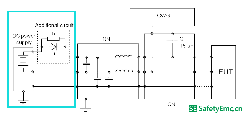
Figure I.1 –Example of adding a damping circuit to the CDN for DC/DC converter EUTs

 苏公网安备32050802011615号